Rendering 360° Photos: From Equirectangular Pixels to a View
A walkthrough of the math, coordinate systems, and projection code you need to show an equirectangular panorama on screen.
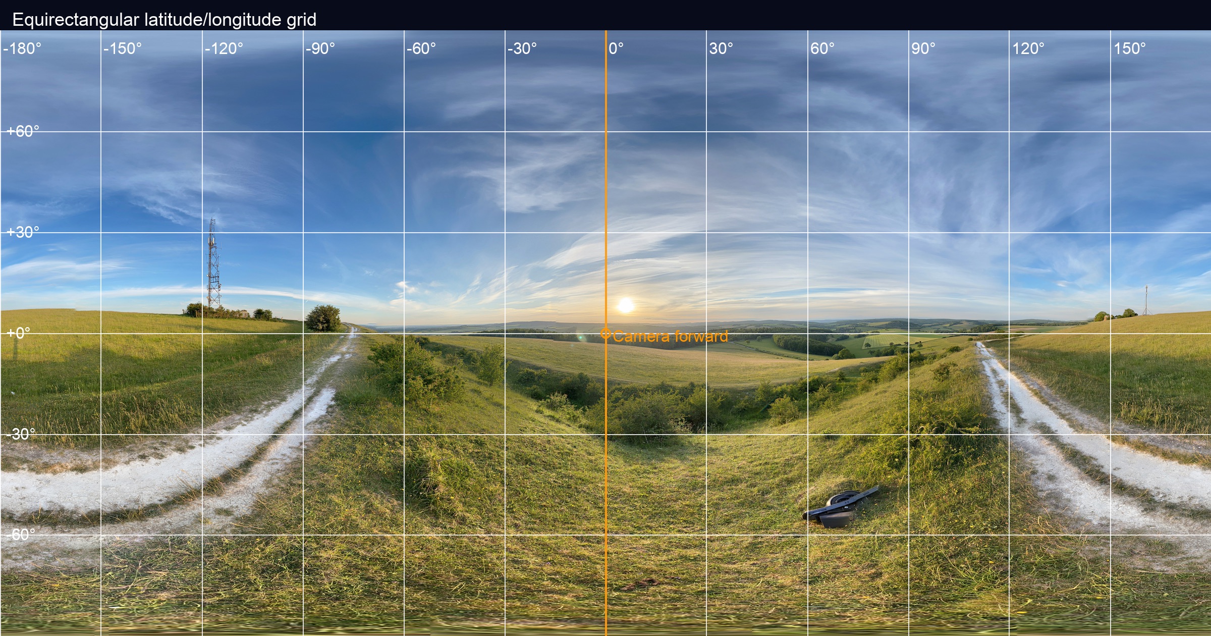
Figure 1. Annotated equirectangular source showing meridians, parallels, and the forward camera marker.
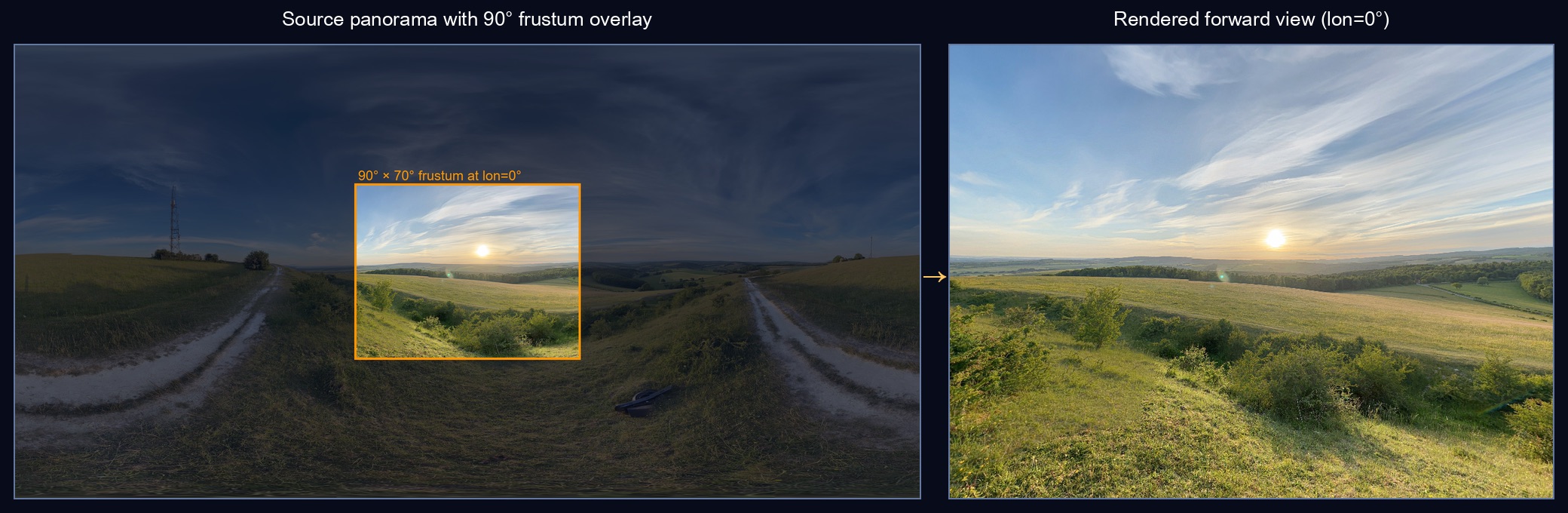
Figure 2. Left: the source panorama with a 90° frustum overlay at the center. Right: the corresponding region rendered as viewed through the virtual camera.
TL;DR — Treat every pixel in an equirectangular panorama as a latitude/longitude sample on the unit sphere. Convert those angles into a direction vector, rotate it by your virtual camera pose, then sample the texture at the corresponding UV. The math is identical whether you're rendering in Metal, SceneKit, Unity, or WebGL.
1. The coordinate system
An equirectangular image is essentially a world map projection applied to a sphere. It encodes (longitude, latitude) over (u, v) texture space:
- Longitude spans
[-π, +π]horizontally (left edge = -180°, right edge = +180°) - Latitude spans
[+π/2, -π/2]vertically (top = north pole, bottom = south pole)
I keep the math straight with this ASCII map:
      u=0        u=0.5       u=1.0
       ↓           ↓           ↓
+90° ┌─────────────────────────┐ v=0   North pole
     │                         │
  0° │  -180°       0°    +180°│ v=0.5  Equator
     │                         │
-90° └─────────────────────────┘ v=1   South pole
The key insight: every pixel in the texture corresponds to a direction in 3D space.
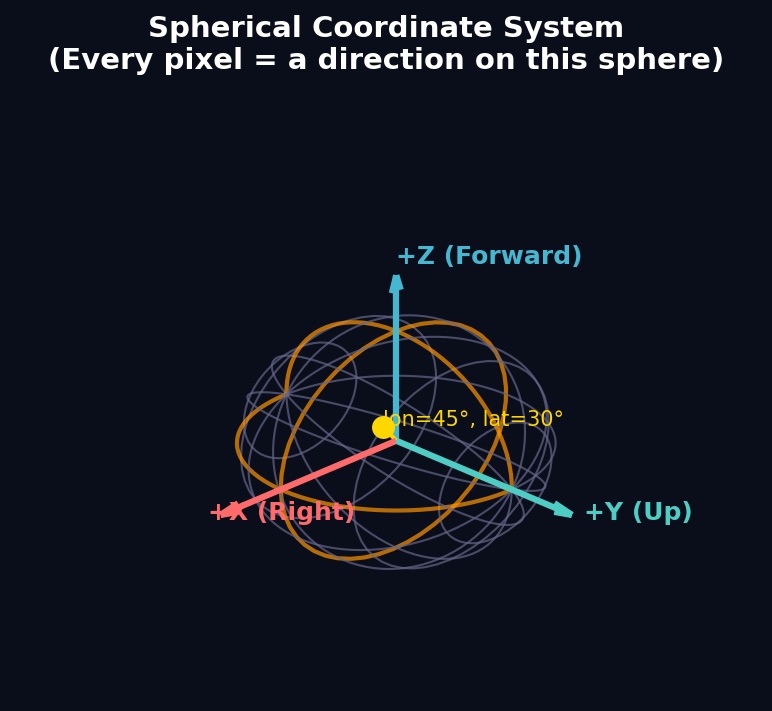
Figure 3. The spherical coordinate system. Every direction on this sphere maps to a unique UV coordinate in the panorama texture.
UV to Direction
Given normalized texture coordinates (u, v) in [0, 1]², first convert to angles:
let longitude = (u - 0.5) * 2.0 * Float.pi  // Range: [-π, +π]
let latitude = (0.5 - v) * Float.pi          // Range: [+π/2, -π/2]
Then convert those spherical coordinates to a Cartesian direction vector:
let direction = SIMD3<Float>(
    cos(latitude) * cos(longitude),  // x: left/right
    sin(latitude),                   // y: up/down
    cos(latitude) * sin(longitude)   // z: forward/back
)
This follows the standard convention where:
- +X points right (longitude = 0°)
- +Y points up (latitude = +90°, north pole)
- +Z points forward (longitude = +90°)
Direction to UV (the inverse)
For rendering, we need the reverse: given a 3D direction, find the texture UV:
func directionToUV(_ direction: SIMD3<Float>) -> SIMD2<Float> {
    let longitude = atan2(direction.z, direction.x)        // Range: [-π, +π]
    let latitude = asin(clamp(direction.y, -1.0, 1.0))     // Range: [-π/2, +π/2]

    let u = (longitude / (2.0 * Float.pi)) + 0.5           // Range: [0, 1]
    let v = 0.5 - (latitude / Float.pi)                    // Range: [0, 1]

    return SIMD2<Float>(u - floor(u), clamp(v, 0.0, 1.0))  // Wrap u, clamp v
}
The u - floor(u) handles wrapping at the ±180° seam, while v gets clamped because the poles are singularities.
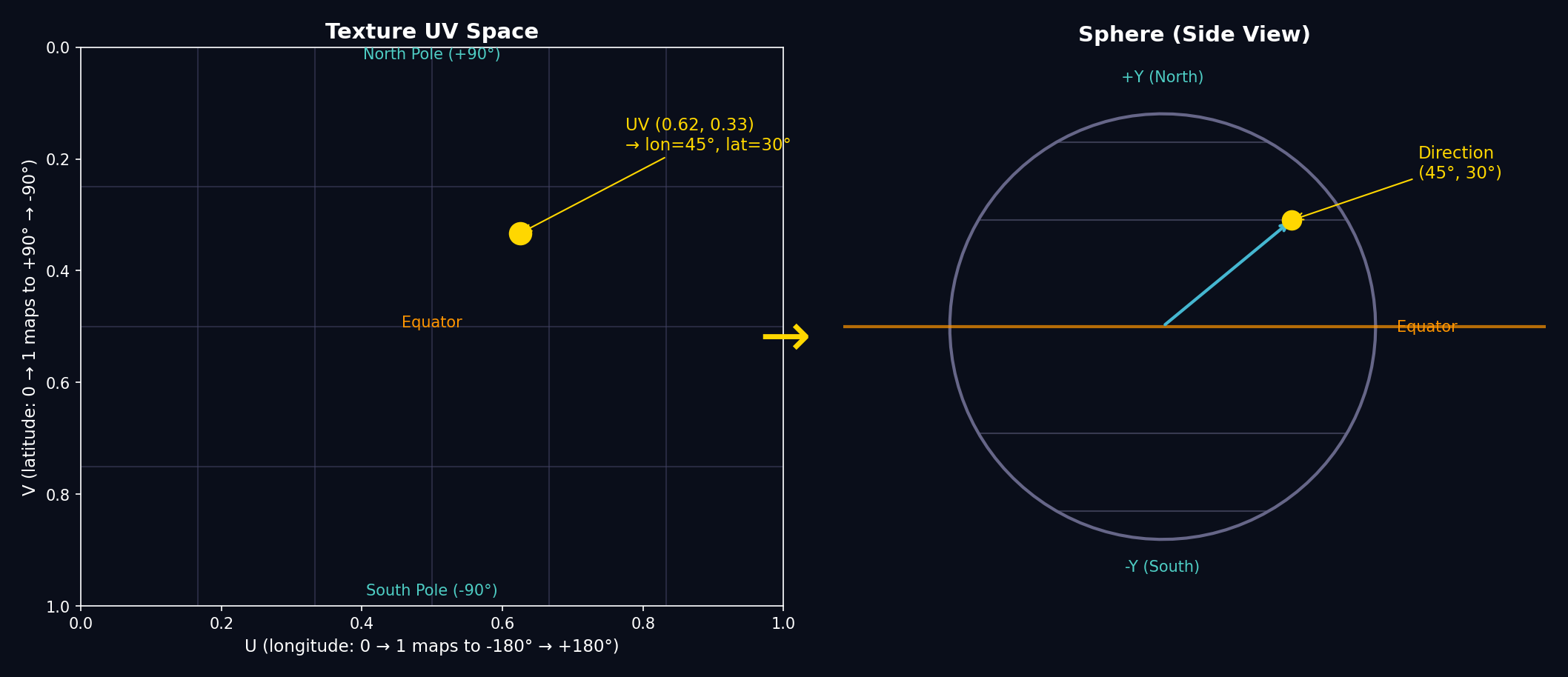
Figure 4. Left: a sample point in UV texture space. Right: the corresponding direction on the sphere.
2. Camera rotation & projection
The camera's orientation is represented as a rotation matrix (or quaternion). To find which direction in the panorama corresponds to a given screen pixel, we work backwards: start from the screen, unproject to a view ray, then rotate into world space.
Screen to view ray
For a pixel at normalized device coordinates (ndcX, ndcY) where (-1, -1) is bottom-left and (1, 1) is top-right:
// Convert screen pixel to NDC
let ndcX = (2.0 * pixelX / viewportWidth) - 1.0
let ndcY = 1.0 - (2.0 * pixelY / viewportHeight)  // Flip Y

// Create view ray (camera looking down -Z axis)
let viewDir = normalize(SIMD3<Float>(
    ndcX * tan(fovX / 2.0),
    ndcY * tan(fovY / 2.0),
    -1.0
))
Rotate to world space
Multiply the view direction by the camera's rotation matrix to get the world-space direction:
let worldDir = (cameraRotationMatrix * SIMD4<Float>(viewDir, 0.0)).xyz
The result is a unit vector pointing from the viewer into the panorama. Pass this to directionToUV() to sample the texture.
The reverse (world to screen)
If you need to project a world direction back to screen coordinates:
func worldToScreen(_ worldDir: SIMD3<Float>,
                   cameraMatrix: simd_float4x4,
                   fov: SIMD2<Float>,
                   viewport: SIMD2<Float>) -> SIMD2<Float>?
{
    // Transform to view space (inverse rotation)
    let invMatrix = cameraMatrix.inverse
    let viewDir = (invMatrix * SIMD4<Float>(worldDir, 0.0)).xyz

    // Behind the camera? Can't project.
    guard viewDir.z < 0 else { return nil }

    // Perspective divide
    let ndcX = viewDir.x / (-viewDir.z * tan(fov.x / 2.0))
    let ndcY = viewDir.y / (-viewDir.z * tan(fov.y / 2.0))

    // NDC to pixels
    let screenX = (ndcX + 1.0) * 0.5 * viewport.x
    let screenY = (1.0 - ndcY) * 0.5 * viewport.y

    return SIMD2<Float>(screenX, screenY)
}
3. Practical shader
Here's a fragment shader I use inside a Metal MTKView to render a full equirectangular image without cubemaps:
fragment float4 equirectangularFragment(VertexOut in [[stage_in]],
                                        constant CameraUniforms &uniforms [[buffer(0)]],
                                        texture2d<float> pano [[texture(0)]],
                                        sampler panoSampler [[sampler(0)]])
{
    float3 viewDir = normalize(float3(
        in.ndc.x * uniforms.tanHalfFov.x,
        in.ndc.y * uniforms.tanHalfFov.y,
        -1.0
    ));
    float3 worldDir = normalize((uniforms.rotationMatrix * float4(viewDir, 0)).xyz);
    float lon = atan2(worldDir.z, worldDir.x);
    float lat = asin(clamp(worldDir.y, -1.0, 1.0));
    float2 uv = float2(
        (lon / (2.0 * M_PI_F)) + 0.5,
        0.5 - (lat / M_PI_F)
    );
    return pano.sample(panoSampler, fract(uv));
}
The CPU just updates uniforms.rotationMatrix from a quaternion every frame.
4. Visualising the math
I like to keep scratch graphics around to sanity-check the orientation math:
 Viewer     Cube Face (forward cam)
    •          ┌──────────────┐
   /|\         │      ↑ y     │
  / | \        │← -x  +z  +x →│
 /  |  \       │      ↓ y     │
/   |   \      └──────────────┘
- Draw the equator and longitudes directly on the source JPEG with Photoshop or Preview annotations. When the shader runs you should see those lines land where you expect.
- Render a tiny minimap (equirectangular) alongside the 3D view. Whenever you drag the camera, highlight the direction vector on the minimap so it's obvious where you're looking.
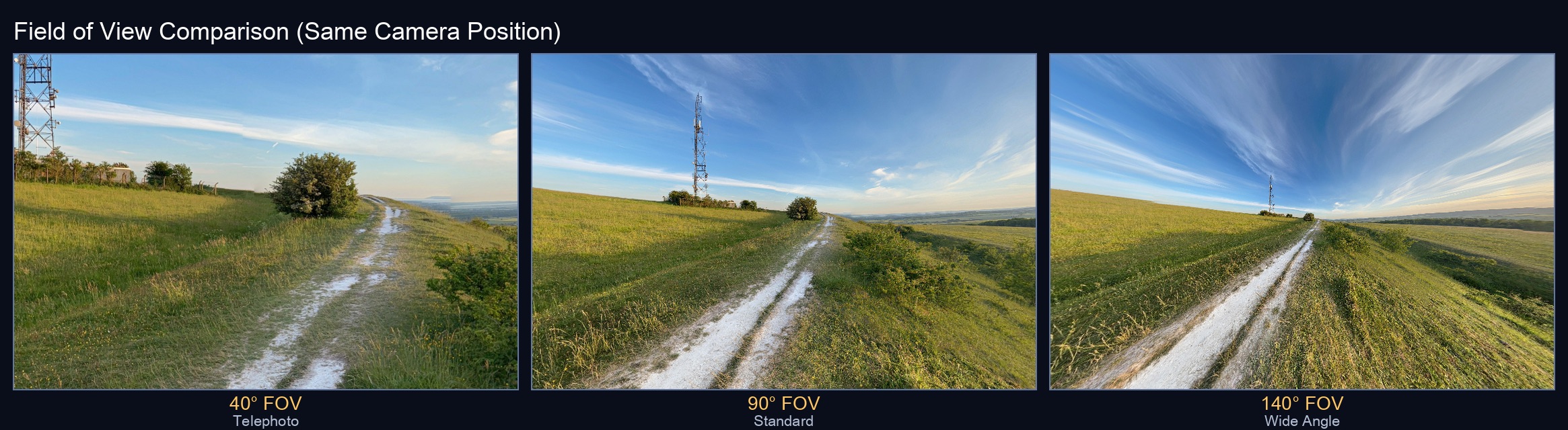
Figure 5. The same camera position rendered at different fields of view. Wider FOV shows more of the panorama but with more distortion at the edges.
5. Sampling only what you see
A 20K×10K panorama is ~758 MB once decoded. You rarely need the entire thing at native resolution. Three approaches:
Approach 1: Direct equirectangular sampling
Load the whole image into a texture2d<float> and let the fragment shader sample directly using directionToUV(). This is the simplest approach, but hits Metal's 16K texture limit on iOS devices (32K on recent Macs).
Approach 2: Pre-bake to cube map (recommended)
Run a compute shader to convert the equirectangular panorama into six cube faces at load time. Rendering then becomes a simple texturecube lookup per pixel:
// In the fragment shader - just one line!
float4 color = cubeTexture.sample(sampler, worldDir);
The cube map conversion uses the same directionToUV() math, but runs once up front rather than every frame. For each pixel in each cube face, we:
- Calculate the world-space direction for that pixel
- Convert to UV coordinates in the source panorama
- Sample and write to the cube face
ASCII view of the six cube faces (unfolded):
          ┌─────┐
          │ +Y  │  (up)
    ┌─────┼─────┼─────┬─────┐
    │ -X  │ +Z  │ +X  │ -Z  │
    └─────┼─────┼─────┴─────┘
          │ -Y  │  (down)
          └─────┘
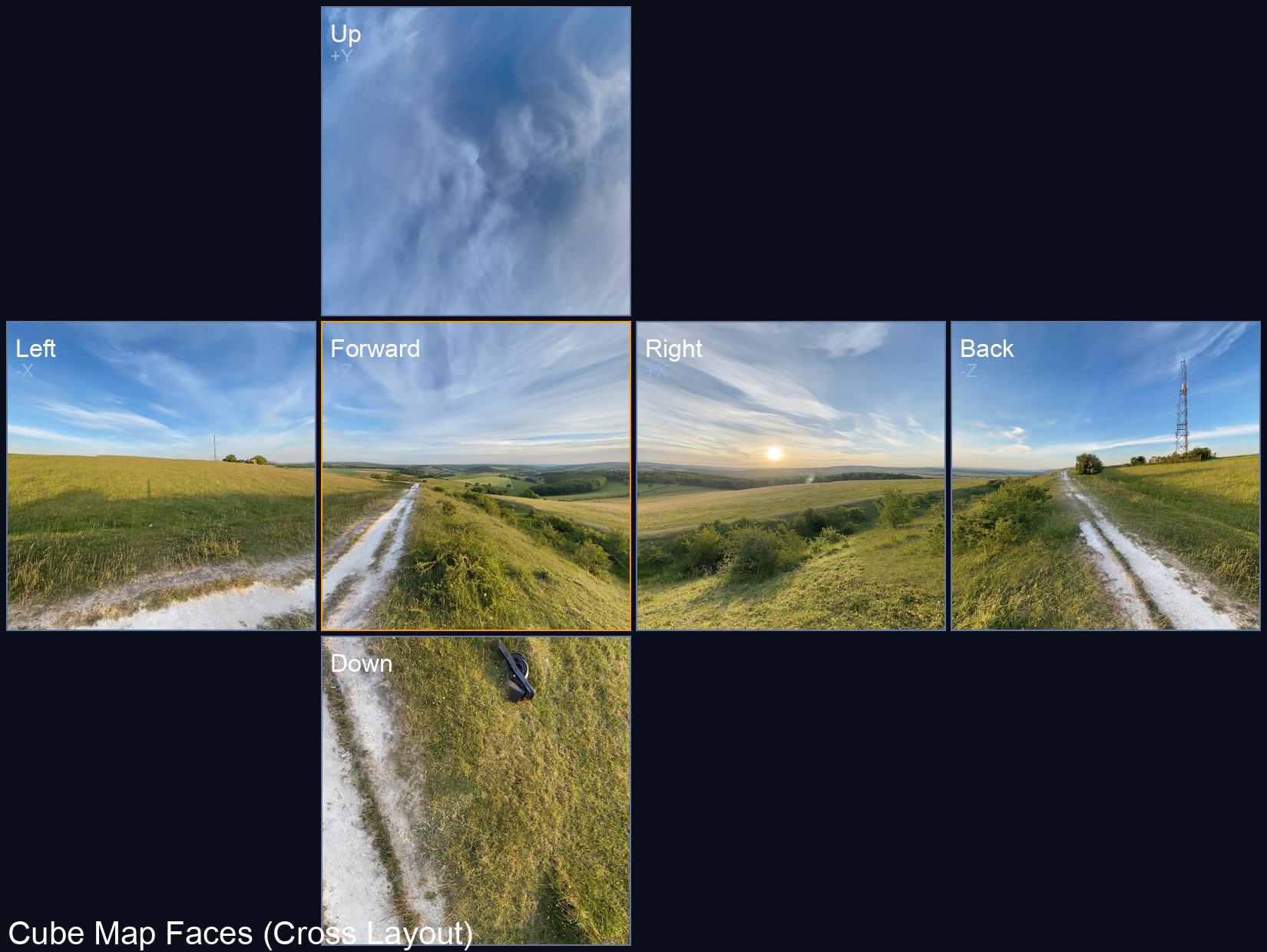
Figure 6. The six cube faces generated from the panorama, arranged in standard cross layout. The +Z (forward) face is highlighted.
This approach saves battery during panning since we're sampling a cube map (which GPUs are highly optimized for) instead of recomputing spherical coordinates per pixel.
Approach 3: Tiled GPU conversion
For panoramas exceeding 16K, we can't upload a single texture. The solution is to split the source image into tiles that each fit within the limit, then sample from multiple textures in the compute shader. See my follow-up post Taming Oversized Panoramas on Metal for the full implementation—we measured ~85× speedup over CPU fallback.
6. Bringing it together in Swift
Now let's connect all these concepts into a working renderer. The architecture has three main pieces:
- A full-screen quad — We draw two triangles that cover the entire screen
- A fragment shader — For each pixel, it calculates which direction we're looking and samples the panorama
- A compute shader — Converts the equirectangular image to a cube map once at load time
6.1 The rendering approach
The trick is that we don't render a 3D sphere. Instead, we render a flat full-screen quad and do all the spherical math in the fragment shader. For each pixel on screen, we:
- Calculate its normalized device coordinates (NDC) from -1 to +1
- Use the FOV to convert that to a view-space ray direction
- Rotate that ray by the camera orientation to get a world direction
- Convert that direction to panorama UV coordinates
- Sample the texture
This is why the vertex shader is trivially simple—it just passes through positions:
vertex VertexOut equirectangularVertex(uint vertexID [[vertex_id]],
                                       constant float2 *positions [[buffer(0)]]) {
    VertexOut out;
    out.position = float4(positions[vertexID], 0.0, 1.0);
    out.ndc = positions[vertexID];  // Pass NDC to fragment shader
    return out;
}
6.2 The fragment shader
The fragment shader does the heavy lifting. It needs two pieces of data from the CPU: the camera's rotation matrix and the tangent of half the field of view (pre-computed to avoid trig in the shader).
struct CameraUniforms {
    float4x4 rotationMatrix;  // Camera orientation as 4x4 matrix
    float2 tanHalfFov;        // tan(fov/2) for x and y, pre-multiplied by aspect ratio
    float2 padding;           // Metal requires 16-byte alignment
};
The shader itself chains together the math from earlier sections:
fragment float4 cubeFragment(VertexOut in [[stage_in]],
                             constant CameraUniforms &uniforms [[buffer(0)]],
                             texturecube<float> cubeTexture [[texture(0)]],
                             sampler textureSampler [[sampler(0)]]) {
    // Step 1: NDC → view ray
    // The tanHalfFov scales the NDC so the edges of the screen
    // correspond to the edges of our field of view
    float3 viewDir = normalize(float3(
        in.ndc.x * uniforms.tanHalfFov.x,
        in.ndc.y * uniforms.tanHalfFov.y,
        -1.0  // Camera looks down -Z
    ));

    // Step 2: Rotate view ray → world direction
    float3 worldDir = normalize((uniforms.rotationMatrix * float4(viewDir, 0)).xyz);

    // Step 3: Sample the cube map
    // GPU hardware handles the direction → face + UV conversion for us!
    return cubeTexture.sample(textureSampler, worldDir);
}
Notice we're sampling a texturecube here, not the equirectangular texture directly. Cube maps are what GPUs are optimized for—the hardware handles converting a 3D direction into the correct face and UV coordinates. That's why we pre-convert the panorama.
6.3 The cube map conversion
The conversion runs once when loading an image. For each pixel on each of the six cube faces, we need to figure out what direction that pixel represents, then sample the equirectangular source at the corresponding UV.
The key insight is that gid.z (the third dimension of our compute grid) represents which cube face we're on:
kernel void equirectangularToCube(
    texture2d<float, access::sample> source [[texture(0)]],
    texturecube<float, access::write> cube [[texture(1)]],
    constant CubeConversionUniforms &uniforms [[buffer(0)]],
    uint3 gid [[thread_position_in_grid]])  // x, y = pixel; z = face index
{
    // Bounds check (compute shaders can overshoot)
    if (gid.x >= uniforms.faceSize || gid.y >= uniforms.faceSize || gid.z >= 6) {
        return;
    }

    // Convert pixel (0..faceSize) to UV (-1..+1) on the cube face
    float2 uv = ((float2(gid.xy) + 0.5) / float(uniforms.faceSize)) * 2.0 - 1.0;

    // Get the 3D direction this pixel represents
    float3 direction = cubeFaceDirection(gid.z, uv);

    // Convert direction → panorama UV, then sample
    float2 panoUV = directionToUV(direction);
    float4 color = source.sample(sampler(filter::linear, address::repeat), panoUV);

    // Write to the cube face
    cube.write(color, uint2(gid.xy), gid.z);
}
The cubeFaceDirection function maps each face to its axis. The pattern is: one component is ±1 (the face's axis), and the other two come from the UV coordinates:
float3 cubeFaceDirection(uint face, float2 uv) {
    switch (face) {
        case 0: return normalize(float3( 1, -uv.y, -uv.x));  // +X face
        case 1: return normalize(float3(-1, -uv.y,  uv.x));  // -X face
        case 2: return normalize(float3(uv.x,  1,  uv.y));   // +Y face (up)
        case 3: return normalize(float3(uv.x, -1, -uv.y));   // -Y face (down)
        case 4: return normalize(float3(uv.x, -uv.y,  1));   // +Z face (front)
        default: return normalize(float3(-uv.x, -uv.y, -1)); // -Z face (back)
    }
}
6.4 Swift: Dispatching the compute shader
On the Swift side, we dispatch one thread per output pixel. The grid is (faceSize × faceSize × 6) to cover all six faces:
// Create the output cube texture
let desc = MTLTextureDescriptor.textureCubeDescriptor(
    pixelFormat: .bgra8Unorm,
    size: faceSize,
    mipmapped: false
)
desc.usage = [.shaderRead, .shaderWrite]
let cubeTexture = device.makeTexture(descriptor: desc)!

// Dispatch the compute shader
let encoder = commandBuffer.makeComputeCommandEncoder()!
encoder.setComputePipelineState(computePipeline)
encoder.setTexture(sourceTexture, index: 0)
encoder.setTexture(cubeTexture, index: 1)
encoder.setBytes(&uniforms, length: MemoryLayout<CubeConversionUniforms>.stride, index: 0)

// One thread per pixel, across all 6 faces
encoder.dispatchThreads(
    MTLSize(width: faceSize, height: faceSize, depth: 6),
    threadsPerThreadgroup: MTLSize(width: 16, height: 16, depth: 1)
)
encoder.endEncoding()
commandBuffer.commit()
commandBuffer.waitUntilCompleted()
6.5 Swift: The render loop
Each frame, we update the camera orientation and render the full-screen quad:
func render(to drawable: MTLTexture) {
    // Convert quaternion orientation to matrix for the shader
    var uniforms = CameraUniforms(
        rotationMatrix: simd_float4x4(orientation),
        tanHalfFov: SIMD2<Float>(
            tan(fovRadians / 2) * aspectRatio,  // X includes aspect ratio
            tan(fovRadians / 2)                  // Y is just the FOV
        )
    )

    let encoder = commandBuffer.makeRenderCommandEncoder(descriptor: passDesc)!
    encoder.setRenderPipelineState(renderPipeline)
    encoder.setVertexBuffer(quadVertexBuffer, offset: 0, index: 0)
    encoder.setFragmentBytes(&uniforms, length: MemoryLayout<CameraUniforms>.stride, index: 0)
    encoder.setFragmentTexture(cubeTexture, index: 0)
    encoder.setFragmentSamplerState(samplerState, index: 0)
    encoder.drawPrimitives(type: .triangle, vertexStart: 0, vertexCount: 6)
    encoder.endEncoding()
}
The quadVertexBuffer contains six vertices forming two triangles that cover clip space from (-1,-1) to (1,1).
6.6 Putting it in a view
Here's how the pieces connect in a minimal Metal-based panorama viewer:
final class PanoramaView: MTKView {

    private var renderer: CubePanoramaRenderer?

    // Camera state
    private var yaw: Float = 0       // Horizontal rotation (radians)
    private var pitch: Float = 0     // Vertical rotation (radians)

    override init(frame: CGRect, device: MTLDevice?) {
        super.init(frame: frame, device: device ?? MTLCreateSystemDefaultDevice())

        self.renderer = CubePanoramaRenderer()
        self.renderer?.fieldOfViewDegrees = 90

        // Enable continuous redraw for smooth interaction
        self.isPaused = false
        self.enableSetNeedsDisplay = false
    }

    override func draw(_ rect: CGRect) {
        guard let drawable = currentDrawable,
              let renderer = renderer
        else { return }

        // Build orientation quaternion from yaw/pitch
        let yawQuat = simd_quatf(angle: yaw, axis: SIMD3<Float>(0, 1, 0))
        let pitchQuat = simd_quatf(angle: pitch, axis: SIMD3<Float>(1, 0, 0))
        renderer.orientation = yawQuat * pitchQuat

        _ = renderer.render(to: drawable.texture, clearColor: clearColor)
        drawable.present()
    }

    func setImage(_ image: UIImage) {
        renderer?.setTexture(from: image)
    }

    // Called by gesture recognizer
    func pan(deltaX: Float, deltaY: Float) {
        let sensitivity: Float = 0.005
        yaw -= deltaX * sensitivity
        pitch = max(-.pi/2, min(.pi/2, pitch - deltaY * sensitivity))
    }

}
The key integration points:
-
Initialization — Create the renderer once; it holds the Metal pipeline state and any converted cube textures.
-
Loading images —
setTexture(from:)handles the equirectangular → cube conversion automatically (GPU path for images within the device's texture limit, tiled path for larger). -
Orientation — Convert user input (pan gestures, device motion) into yaw/pitch angles, then build a quaternion. The renderer multiplies this into the view matrix.
-
Render loop — Each frame, update orientation and call
render(to:). The fragment shader samples the panorama (or cube map) using the math from sections 1–3.
For snapshots or thumbnails, use makeSnapshot(width:height:) which renders to an offscreen texture and returns a CGImage.
The math here is the same whether you target Metal, SceneKit, Unity, or WebGL. If you can turn (u, v) into (lon, lat) and then into a view ray, you can show a convincing 360° photo on any screen.
7. Further reading
- Taming Oversized Panoramas on Metal — my follow-up post on GPU tiling for images exceeding the 16K texture limit